Posts

DARLINGTON TRANSISTOR

  A Darlington transistor circuit is a combination of two bipolar transistors connected in such a way as to provide a high current gain. Advantages: High current gain High input impedance High voltage amplification Drawbacks: High voltage drop High power dissipation High thermal resistance Applications: Power amplification Motor control High voltage switching Challenges: Heat dissipation Stability of the circuit Numerical: High current gain: typically 1000 or more Formula: Common emitter current gain (beta) of Darlington transistor circuit = β1 * β2, where β1 and β2 are the current gains of the individual transistors. Derivation: Darlington transistor circuit is derived from the basic bipolar transistor configuration. Frequency range: The frequency range of Darlington transistor circuit depends on the individual transistors used and can range from a few Hz to several MHz. Year of discovery: Darlington transistor was invented by Sidney Darlington in 1953. Waveform: The waveform of D...
  "The Future of Electrical and Electronics Engineering: A Look into Emerging Technologies"

AMOGHA. A. K. Blog: Website, Apps, Podcasts, YouTube, Google Chrome Extension, Book and Survey Form

Image
AMOGHA. A. K. : Electrical and Electronics Engineering website/ blog is available. To visit, click below: Electrical and Electronics Engineering Website/ Blog AMOGHA. A. K. : Electrical and Electronics Engineering app is available. To download, click below: Electrical and Electronics Engineering App AMOGHA. A. K. : Electrical and Electronics Engineering Quiz app “Amogha A K Quiz EEE” is available on Samsung Galaxy Store Apps. To visit and download, click below: Electrical and Electronics Engineering Quiz App Electrical and Electronics Engineering Quiz app  “Amogha A K Quiz EEE” is also available on Apkpure. To visit and download, click below: Electrical and Electronics Engineering Quiz App AMOGHA. A. K. : Electrical and Electronics Engineering podcasts are available. Listen to Podcasts on various platforms at Apple Podcasts, Google Podcasts, Anchor, Breaker, Overcast, Pocket Casts, RadioPublic and Spotify etc.   To visit, click below: Electrical and Electronics Engineerin...

ELECTRICAL ENGINEERING BOOK

Image

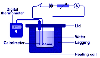
Joule's law

Image
Joule's law It states that the heat produced by an electric current  i  flowing through a resistance  R  for a time  t  is proportional to  i   2   Rt . Hope you found this post  helpful.

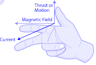
Fleming's Right Hand Rule

Image
  Fleming's Right Hand Rule This law helps to find the  direction of induced current in the conductor when a conductor moves in the magnetic field. If we strech the fingers of right hand, then Thumb represents the direction of motion. Index finger represents the direction of magnetic field. Middle finger represents the direction of induced current in the conductor. Hope you found this post helpful.

Fleming's Left Hand Rule

Image
  Fleming's Left Hand Rule It states that i f a conductor is placed in magnetic field and current is flowing through it, then it will experience a force which is mutually perpendicular to the field and current. If we stretch the fingers of left hand, then Index finger will represent the direction of magnetic field. Middle finger shows the direction of current. Thumb represents the direction of force. Hope you found this post helpful.