Posts

Showing posts from November, 2020

DARLINGTON TRANSISTOR

  A Darlington transistor circuit is a combination of two bipolar transistors connected in such a way as to provide a high current gain. Advantages: High current gain High input impedance High voltage amplification Drawbacks: High voltage drop High power dissipation High thermal resistance Applications: Power amplification Motor control High voltage switching Challenges: Heat dissipation Stability of the circuit Numerical: High current gain: typically 1000 or more Formula: Common emitter current gain (beta) of Darlington transistor circuit = β1 * β2, where β1 and β2 are the current gains of the individual transistors. Derivation: Darlington transistor circuit is derived from the basic bipolar transistor configuration. Frequency range: The frequency range of Darlington transistor circuit depends on the individual transistors used and can range from a few Hz to several MHz. Year of discovery: Darlington transistor was invented by Sidney Darlington in 1953. Waveform: The waveform of D...
Joule's law

Image
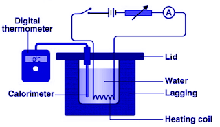
Joule's law It states that the heat produced by an electric current  i  flowing through a resistance  R  for a time  t  is proportional to  i   2   Rt . Hope you found this post  helpful.

Fleming's Right Hand Rule

Image
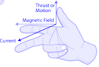
  Fleming's Right Hand Rule This law helps to find the  direction of induced current in the conductor when a conductor moves in the magnetic field. If we strech the fingers of right hand, then Thumb represents the direction of motion. Index finger represents the direction of magnetic field. Middle finger represents the direction of induced current in the conductor. Hope you found this post helpful.

Fleming's Left Hand Rule

Image
  Fleming's Left Hand Rule It states that i f a conductor is placed in magnetic field and current is flowing through it, then it will experience a force which is mutually perpendicular to the field and current. If we stretch the fingers of left hand, then Index finger will represent the direction of magnetic field. Middle finger shows the direction of current. Thumb represents the direction of force. Hope you found this post helpful.

Faraday's Law

Image
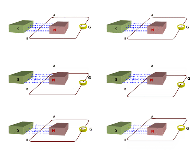
Faraday's law of induction/ Faraday's law It is a basic law of electromagnetism predicting how a magnetic field will interact with an electric circuit to produce an electromotive force (EMF)—a phenomenon known as electromagnetic induction . Faraday's first law of electromagnetic induction   Whenever a conductor is placed in a varying magnetic field, an electromotive force is induced. If the conductor circuit is closed, a current is induced which is called induced current. Faraday’s second law of electromagnetic induction It states that the induced emf in a coil is equal to the rate of change of flux linkage. Hope you found this post useful.

Gauss law

Image
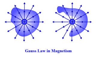
  Gauss Law It states that the electric flux through any closed surface is proportional to the total electric charge enclosed by this surface. Hope you found this post helpful.

Wiedemann- Franz Law

Image
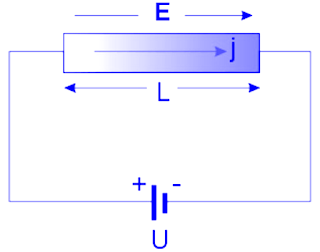
Wiedemann–Franz law  It states that the ratio of the electronic contribution of the thermal conductivity to the electrical conductivity of a metal is proportional to the temperature. Hope you found this post helpful.

Ampere's Circuital Law

Image
Ampere's circuital law It states that the closed line integral of magnetic field around a current carrying conductor is equal to absolute permeability times the total current threading the conductor. Hope you found this post helpful.